566添加DPI-LCD实例
1 确认rt-driver工程正常运行
It is recommended to use the rt-driver project for screen adjustment, and confirm that the rt-driver project can run normally and has Log printing before debugging
1.1 编译
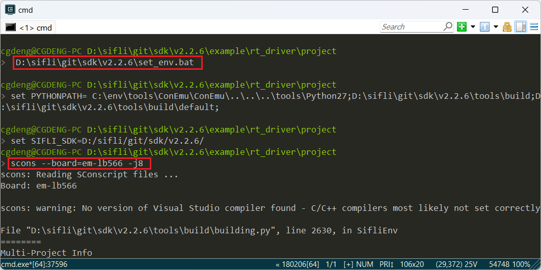
Enter the example\rt_driver\project directory, right-click to select ComEmu_Here to pop up the compilation command serial port, and execute in sequence
>  D:\sifli\git\sdk\v2.2.6\set_env.bat   #Set compilation environment path
> scons --board=em-lb566 -j8  #Specify em-lb566 module to compile rt-driver project
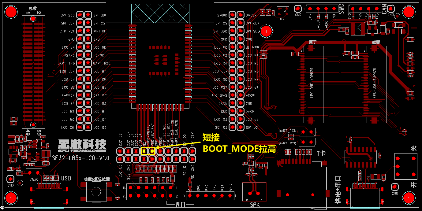
1.2 进入BOOT模式
BOOT_MODE is pulled up to 3.3V, 566 enters boot mode for easy downloading,如下图的BOOT_MODE短接拉高到3.3V
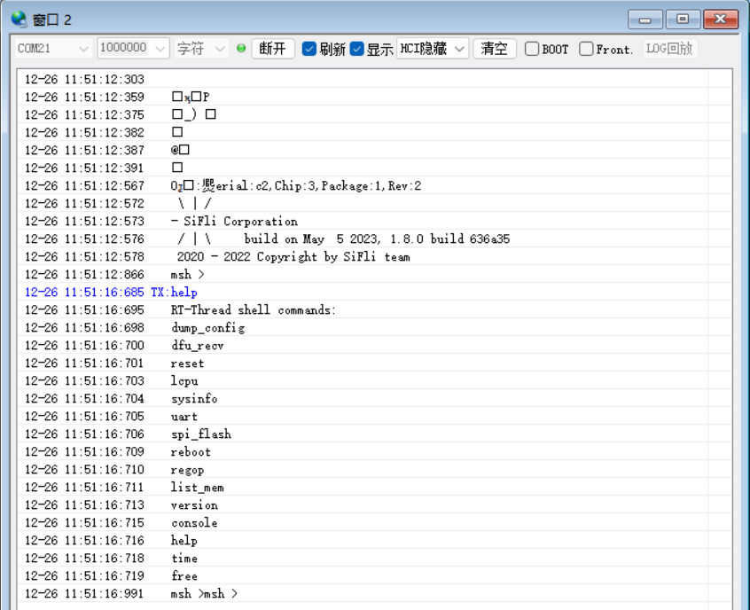
After entering the boot mode, the serial port will output the following Log. If you input the command help, there will also be Log output, indicating that the serial port MCU is running normally and the serial communication is normal. Click to disconnect the serial port and prepare for downloading
1.3 下载
> build_em-lb566\uart_download.bat

     Uart Download

please input the serial port num:21 #然后选择1.2步骤中验证可以输出Log的串口号进行下载
1.4 确认正常LOG
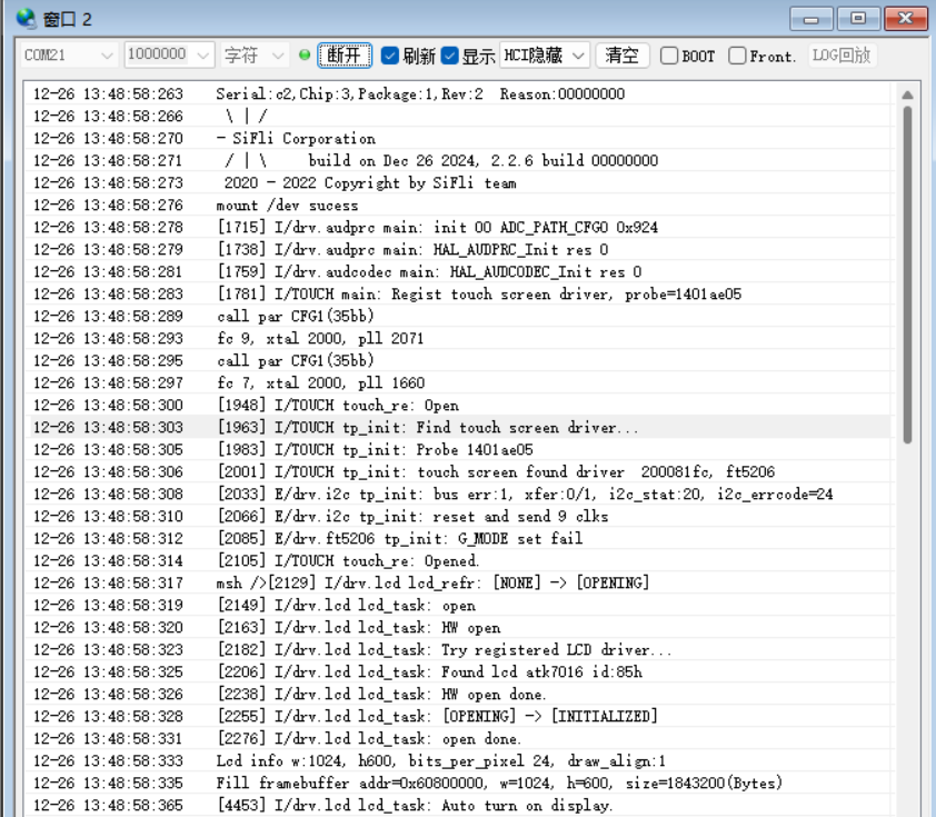
Remove the short-circuit jumper in step 1.2, power on reset, let the MCU run the user program, if the following Log is output, it means the development board has been running normally, then you can continue to the next step to add a new screen module
2 添加屏驱NV3052C
2.1 创建NV3052C驱动
1) 屏驱位置
The screen driver is located in the sdk\customer\peripherals directory
2) 复制驱动
Copy a driver of another dpi interface and rename it as dpi_nv3052c
2.2 Menuconfig添加NV3052C
1) 修改Kconfig在menuconfig中生成该屏的选项
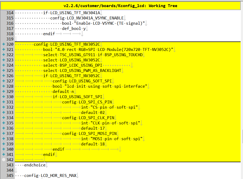
Open sdk\customer\boards\Kconfig_lcd with a text editor, add an option and resolution for DPI screen as follows
# menuconfig 生成菜单呈现的选项
        config LCD_USING_TFT_NV3052C
            bool "4.0 rect RGB+SPI LCD Module(720x720 TFT-NV3052C)"     #Characters displayed in menuconfig
			select TSC_USING_GT911 if BSP_USING_TOUCHD      #If TP is available, it can be opened. Whether the corresponding TP driver is compiled depends on this macro
            select LCD_USING_NV3052C        #Whether the files in the spi_nv3052c folder are compiled depends on this macro
            select BSP_LCDC_USING_DPI       #Select DPI interface
            select LCD_USING_PWM_AS_BACKLIGHT #Whether to turn on the PWM backlight of the screen, screens with backlight need to be turned on
			if LCD_USING_TFT_NV3052C
				config LCD_USING_SOFT_SPI #Select whether the DPI screen needs SPI for initialization
                bool "lcd init using soft spi interface" #Characters displayed in menuconfig
                default n
				if LCD_USING_SOFT_SPI
					config LCD_SPI_CS_PIN # CS pin of software SPI
							int "CS pin of soft spi" #Characters displayed in menuconfig
							default 02 #默认PA02
					config LCD_SPI_CLK_PIN  # CLK pin of software SPI
							int "CLK pin of soft spi" #Characters displayed in menuconfig
							default 17 #默认PA17,如果PB口+96,例如PB02这里配置为98
					config LCD_SPI_MOSI_PIN # MOSI pin of software SPI
							int "MOSI pin of soft spi" #Characters displayed in menuconfig
							default 18 #默认PA18
				endif
			endif
# LCD_HOR_RES_MAX is configured as the horizontal resolution of the screen
        default 720 if LCD_USING_TFT_NV3052C
# LCD_VER_RES_MAX is configured as the vertical resolution of the screen
        default 720 if LCD_USING_TFT_NV3052C
# LCD_DPI pixel density, how many pixels per inch of the screen, fill in the default 315 if unknown
        default 315 if LCD_USING_TFT_NV3052C
2) LCD_USING_NV3052C添加
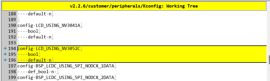
文本编辑器打开文件sdk\customer\peripherals\Kconfig,添加如下
config LCD_USING_NV3052C #添加该配置,Kconfig中才能select上
    bool
    default n
3) SConscript修改
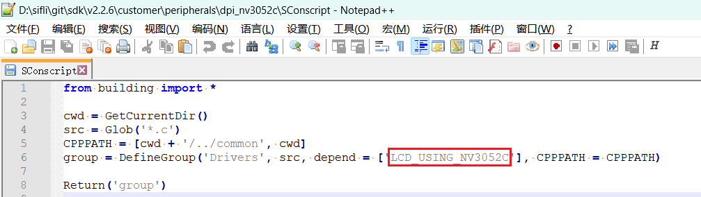
Open the file customer\peripherals\dpi_nv3052c\SConscript with a text editor, modify the macro LCD_USING_NV3052C, so that the *.c and *.h files in this directory can be added to the compilation
2.3 Menuconfig选中NV3052C
After completing the above steps, enter the following command in the compilation window and select the newly added nv3052c screen
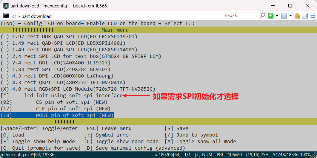
menuconfig --board=em-lb566(打开menuconfig窗口) In this path(Top) → Config LCD on board → Enable LCD on the board → Select LCD, select the newly added screen. As shown in the example below, if the DPI screen has an SPI interface that needs to be initialized, only then selectlcd init using soft spi interface, and configure the three IO ports used by SPI. After saving and exiting, the screen driver under the dpi_nv3052c directory is selected to participate in the compilation
3 生成SourceInsight工程
In order to easily view the code participating in the compilation, you can generate a list of files for the entire rt-driver project to participate in the compilation, and then import it into Source Insight for easy viewing. This chapter can be skipped
1 生成文件List
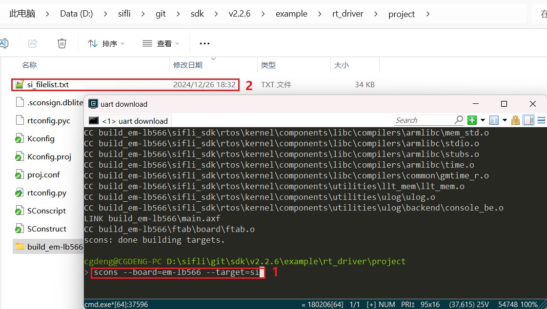
The command scons --board=em-lb566 --target=si generates si_filelist.txt
2 文件List导入
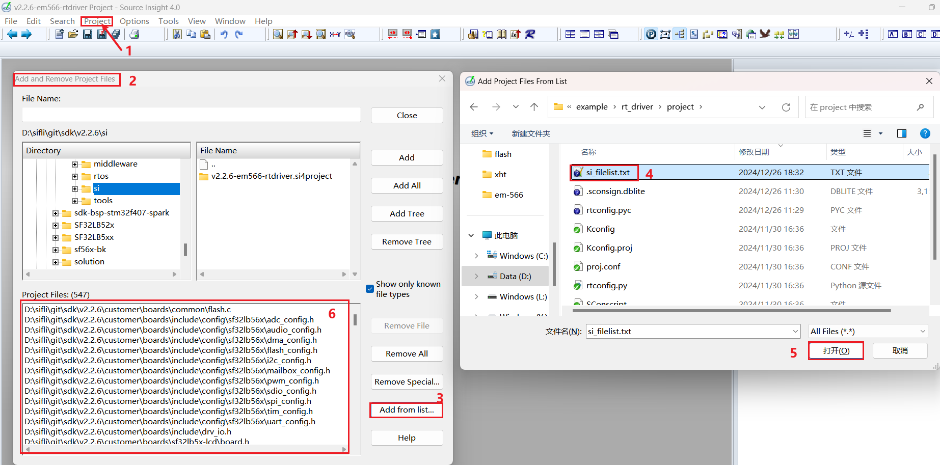
Open Source Insight to import si_filelist.txt into the project
3 查看屏驱是否生效
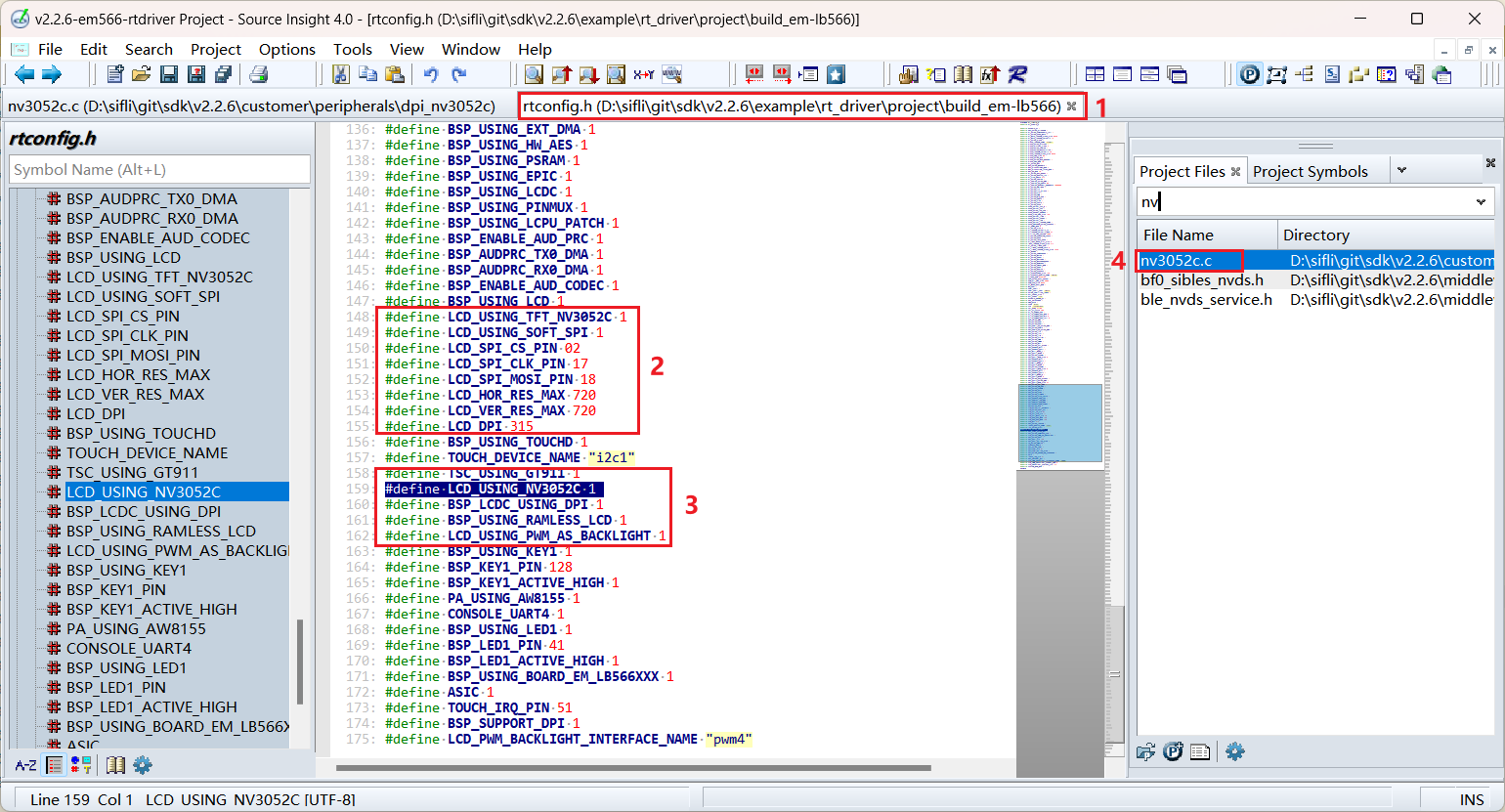
You can check in the SI (Source Insight) project whether the corresponding macro in rtconfig.h is generated and whether dpi_nv3052c.c has been included in the compilation
4 屏硬件连接
4.1 排线连接
If you purchase a matching screen module, just connect the ribbon cable to the socket
4.2 飞线连接
If the new screen module has inconsistent ribbon cable arrangement, you need to design your own ribbon cable adapter board or debug from the pin flying wires。
The design of the adapter board can refer to SF32LB52-DevKit-LCD Adapter Board Production Guide
5 屏驱动配置
5.1 默认IO配置
If the default IO is used, this part can be skipped
5.1.1 IO模式设置
LCD uses LCDC1 hardware to output waveforms and needs to be configured to the corresponding FUNC mode,
For each IO, you can refer to the hardware documentation for its functions 下载SF32LB56X_Pin_config
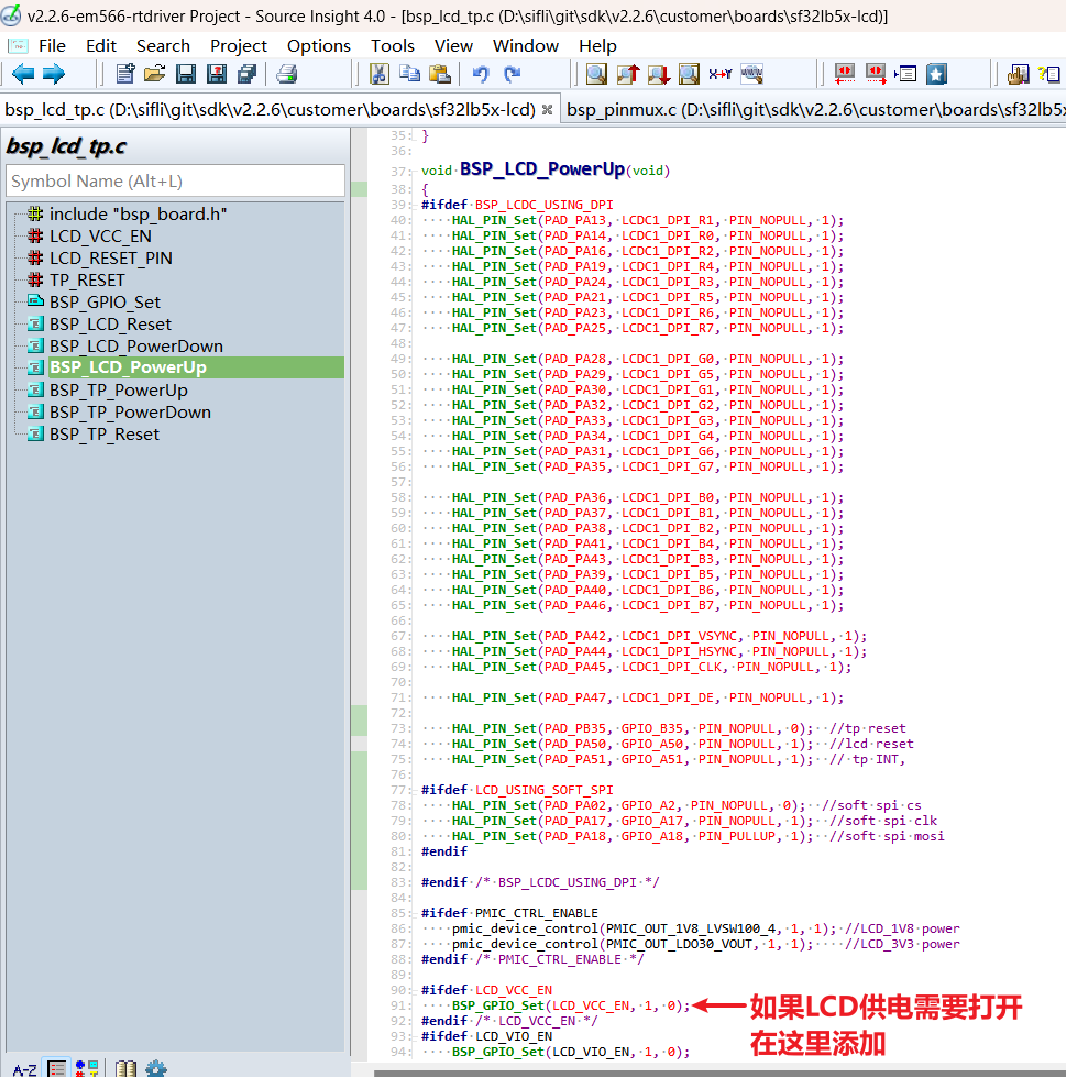
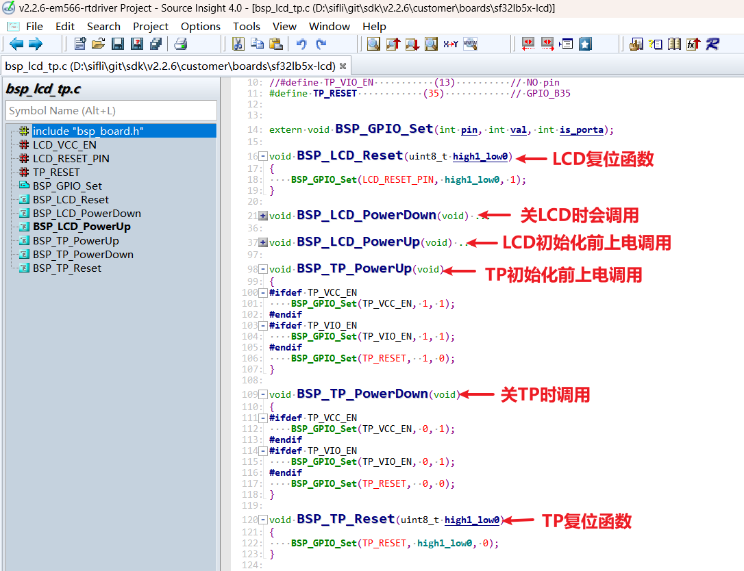
The RESET pins of the LCD and TP both use GPIO mode, which is already configured as GPIO mode by default. If the LCD power supply needs to be turned on separately, it also needs to be turned on here
void BSP_LCD_PowerUp(void)
{
#ifdef BSP_LCDC_USING_DPI
    HAL_PIN_Set(PAD_PA13, LCDC1_DPI_R1, PIN_NOPULL, 1);
    HAL_PIN_Set(PAD_PA14, LCDC1_DPI_R0, PIN_NOPULL, 1);
    HAL_PIN_Set(PAD_PA16, LCDC1_DPI_R2, PIN_NOPULL, 1);
    HAL_PIN_Set(PAD_PA19, LCDC1_DPI_R4, PIN_NOPULL, 1);
    HAL_PIN_Set(PAD_PA24, LCDC1_DPI_R3, PIN_NOPULL, 1);
    HAL_PIN_Set(PAD_PA21, LCDC1_DPI_R5, PIN_NOPULL, 1);
    HAL_PIN_Set(PAD_PA23, LCDC1_DPI_R6, PIN_NOPULL, 1);
    HAL_PIN_Set(PAD_PA25, LCDC1_DPI_R7, PIN_NOPULL, 1);

    HAL_PIN_Set(PAD_PA28, LCDC1_DPI_G0, PIN_NOPULL, 1);
    HAL_PIN_Set(PAD_PA29, LCDC1_DPI_G5, PIN_NOPULL, 1);
    HAL_PIN_Set(PAD_PA30, LCDC1_DPI_G1, PIN_NOPULL, 1);
    HAL_PIN_Set(PAD_PA32, LCDC1_DPI_G2, PIN_NOPULL, 1);
    HAL_PIN_Set(PAD_PA33, LCDC1_DPI_G3, PIN_NOPULL, 1);
    HAL_PIN_Set(PAD_PA34, LCDC1_DPI_G4, PIN_NOPULL, 1);
    HAL_PIN_Set(PAD_PA31, LCDC1_DPI_G6, PIN_NOPULL, 1);
    HAL_PIN_Set(PAD_PA35, LCDC1_DPI_G7, PIN_NOPULL, 1);

    HAL_PIN_Set(PAD_PA36, LCDC1_DPI_B0, PIN_NOPULL, 1);
    HAL_PIN_Set(PAD_PA37, LCDC1_DPI_B1, PIN_NOPULL, 1);
    HAL_PIN_Set(PAD_PA38, LCDC1_DPI_B2, PIN_NOPULL, 1);
    HAL_PIN_Set(PAD_PA41, LCDC1_DPI_B4, PIN_NOPULL, 1);
    HAL_PIN_Set(PAD_PA43, LCDC1_DPI_B3, PIN_NOPULL, 1);
    HAL_PIN_Set(PAD_PA39, LCDC1_DPI_B5, PIN_NOPULL, 1);
    HAL_PIN_Set(PAD_PA40, LCDC1_DPI_B6, PIN_NOPULL, 1);
    HAL_PIN_Set(PAD_PA46, LCDC1_DPI_B7, PIN_NOPULL, 1);

    HAL_PIN_Set(PAD_PA42, LCDC1_DPI_VSYNC, PIN_NOPULL, 1);
    HAL_PIN_Set(PAD_PA44, LCDC1_DPI_HSYNC, PIN_NOPULL, 1);
    HAL_PIN_Set(PAD_PA45, LCDC1_DPI_CLK, PIN_NOPULL, 1);

    HAL_PIN_Set(PAD_PA47, LCDC1_DPI_DE, PIN_NOPULL, 1);

    HAL_PIN_Set(PAD_PB35, GPIO_B35, PIN_NOPULL, 0);    // tp reset
    HAL_PIN_Set(PAD_PA50, GPIO_A50, PIN_NOPULL, 1);    // lcd reset
    HAL_PIN_Set(PAD_PA51, GPIO_A51, PIN_NOPULL, 1);    // tp INT,

#ifdef LCD_USING_SOFT_SPI
    HAL_PIN_Set(PAD_PA02, GPIO_A2, PIN_NOPULL, 0);     // soft spi cs
    HAL_PIN_Set(PAD_PA17, GPIO_A17, PIN_NOPULL, 1);    // soft spi clk
    HAL_PIN_Set(PAD_PA18, GPIO_A18, PIN_PULLUP, 1);    // soft spi mosi
#endif

#endif /* BSP_LCDC_USING_DPI */

#ifdef PMIC_CTRL_ENABLE
    pmic_device_control(PMIC_OUT_1V8_LVSW100_4, 1, 1); // LCD_1V8 power
    pmic_device_control(PMIC_OUT_LDO30_VOUT, 1, 1);    // LCD_3V3 power
#endif /* PMIC_CTRL_ENABLE */

#ifdef LCD_VCC_EN
    BSP_GPIO_Set(LCD_VCC_EN, 1, 0);                    //如果LCD供电需要打开,在这里添加
#endif /* LCD_VCC_EN */
#ifdef LCD_VIO_EN
    BSP_GPIO_Set(LCD_VIO_EN, 1, 0);
#endif
}
5.1.2 IO上下电操作
The following is the power-on LCD initialization process
rt_hw_lcd_ini->api_lcd_init->lcd_task->lcd_hw_open->BSP_LCD_PowerUp-find_right_driver->LCD_drv.LCD_Init->LCD_drv.LCD_ReadID->lcd_set_brightness->LCD_drv.LCD_DisplayOn
可以看到上电BSP_LCD_PowerUp在屏驱动初始化LCD_drv.LCD_Init之前
Therefore, before initializing the LCD, ensure that the LCD power supply has been turned on in BSP_LCD_PowerUp
5.1.3 Backlight PWM configuration
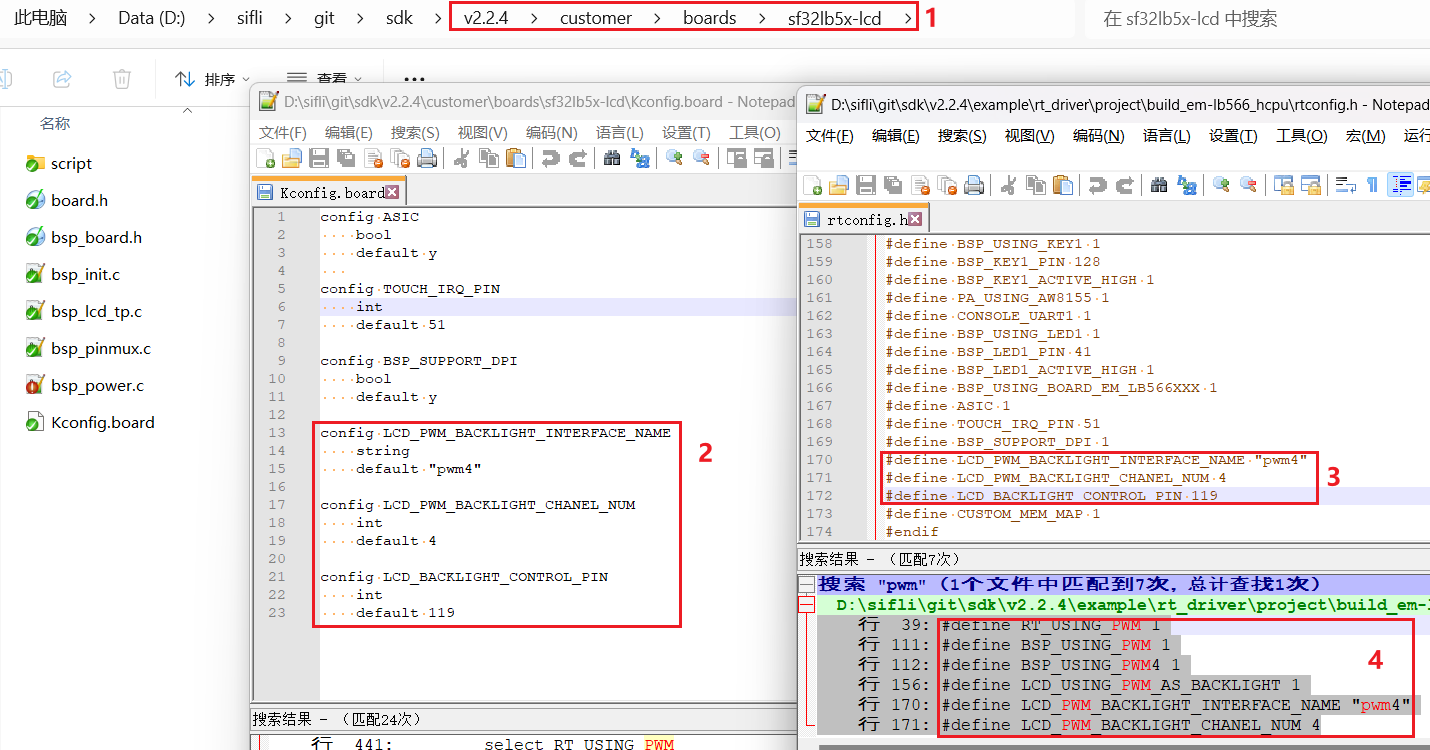
pwm软件中有一个默认配置,配置在文件customer\boards\sf32lb5x-lcd\Kconfig.board中,此Kconfig.board的配置会编译后在rtconfig.h中生成下面3个宏
//PWM4需要打开GPTIM3,PWM和TIMER对应关系,可以查看FAQ的PWM部分或者文件`pwm_config.h`<br>
#define LCD_PWM_BACKLIGHT_INTERFACE_NAME "pwm3"
#define LCD_PWM_BACKLIGHT_CHANEL_NUM 4 //Channel 4
#define LCD_BACKLIGHT_CONTROL_PIN 119 //PB23: 96+23
用PWM4需要打开GPTIM3,Lcpu中也需要打开(否则Lcpu可能会关掉GPTIM3),还需确认rtconfig.h下面宏是否生效
#define BSP_USING_GPTIM3 1 //如果用PWM3,需要menuconfig --board=em-lb566打开
#define RT_USING_PWM 1
#define BSP_USING_PWM 1
#define BSP_USING_PWM4 1 //如果没有,需要menuconfig --board=em-lb566打开
如下文件pwm_config.h中pwm4和GPTIM3(位于Lcpu)的对应关系
#ifdef BSP_USING_PWM4
#define PWM4_CONFIG                             \
    {                                           \
       .tim_handle.Instance     = GPTIM3,         \
       .tim_handle.core         = PWM4_CORE,    \
       .name                    = "pwm4",       \
       .channel                 = 0             \
    }
#endif /* BSP_USING_PWM4 */
The software defaults PB23 to output PWM waveform from the "pwm4" device of GPTIM3, with default configuration at
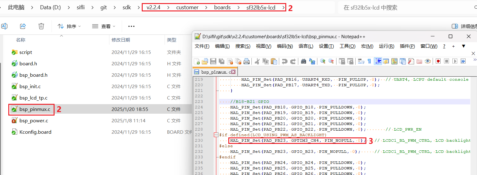
HAL_PIN_Set(PAD_PB23, GPTIM3_CH4, PIN_NOPULL, 0); // LCDC1_BL_PWM_CTRL, LCD backlight PWM
备注:
After configuring through the function HAL_PIN_Set, the corresponding relationship between GPTIM3_CH4 and PB23 will be established, specifically reflected in the register configuration hwp_lpsys_cfg->GPTIM3_PINR,如下图:
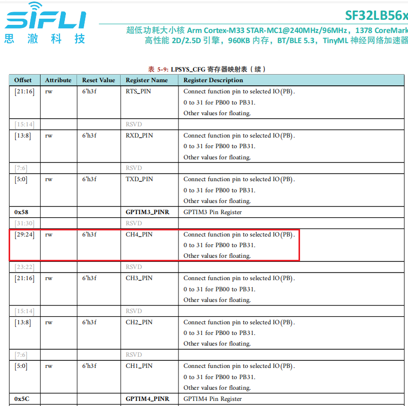
It can be seen that it can be configured to output CH1-CH4, and it must be the PB00-PB31 port. Additionally, Hcpu uses Lcpu’s TIMER resources, so Lcpu also needs to enable #define BSP_USING_GPTIM3 1. Otherwise, in the early SDK code drv_common.c, RCC_MOD_GPTIM3 will be turned off, resulting in no output for PWM4
#if !defined(BSP_USING_GPTIM3) && !defined(BSP_USING_PWM4)
    HAL_RCC_DisableModule(RCC_MOD_GPTIM3); //关闭GPTIM3的时钟
#endif /* !BSP_USING_GPTIM3 */
5.2 屏驱复位时序
In nv3052c.c, the following delays in the LCD_Init function are critical. They need to refer to the initialization timing of the screen driver IC related documents and modify them cautiously
    BSP_LCD_Reset(1);
    rt_thread_delay(10);
    BSP_LCD_Reset(0);       //Reset LCD
    rt_thread_delay(5);
    BSP_LCD_Reset(1);
    rt_thread_delay(80);
5.3 屏驱寄存器修改
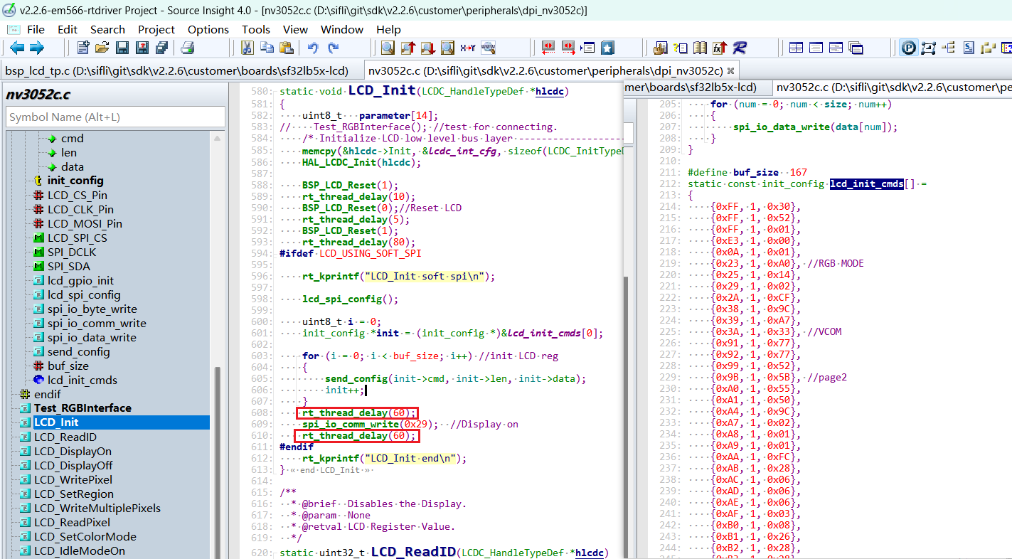
Some DPI interface screens do not require SPI or initialization, and there is no need to enable the macro LCD_USING_SOFT_SPI. After the screen driver IC is powered on and reset, data can be sent to the RGB data line. Some DPI screens require initial configuration parameters using the SPI interface first. The initialization register configuration for each screen driver IC is different, and it is necessary to write to the screen driver IC according to the register parameters provided by the screen manufacturer and their SPI timing. Pay special attention to the delay length requirements after registers 0x11 and 0x29
static void LCD_Init(LCDC_HandleTypeDef *hlcdc)
{
...
#ifdef LCD_USING_SOFT_SPI

    rt_kprintf("LCD_Init soft spi\n");

    lcd_spi_config();

    uint8_t i = 0;
    init_config *init = (init_config *)&lcd_init_cmds[0];

    for (i = 0; i < buf_size; i++)   //init LCD reg
    {
        send_config(init->cmd, init->len, init->data);
        init++;
    }
    rt_thread_delay(60);
    spi_io_comm_write(0x29);         //Display on
    rt_thread_delay(60);
#endif
    rt_kprintf("LCD_Init end\n");
}
5.4 屏驱参数配置
.lcd_itf: Select LCDC_INTF_DPI_AUX to indicate DPI interface mode
.freq: Choose 35 * 1000 * 1000, indicating that the main frequency of DPI clk is 35Mhz. This clock should be selected based on the highest clock supported by the screen driver IC. The higher the clock, the shorter the time to send each frame, and the higher the frame rate
.color_mode: Choose between RGB565 or RGB888 format
static LCDC_InitTypeDef lcdc_int_cfg =
{
    .lcd_itf = LCDC_INTF_DPI_AUX,
    .freq = 35 * 1000 * 1000,
    .color_mode = LCDC_PIXEL_FORMAT_RGB888,

    .cfg = {
        .dpi = {
            .PCLK_polarity = 0,
            .DE_polarity   = 0,
            .VS_polarity   = 1,
            .HS_polarity   = 1,
            .PCLK_force_on = 0,

            .VS_width      = 5,    // VLW
            .HS_width      = 2,    // HLW

            .VBP = 15,             // VBP
            .VAH = 720,
            .VFP = 16,             // VFP

            .HBP = 44,             // HBP
            .HAW = 720,
            .HFP = 44,             // HFP

            .interrupt_line_num = 1,
        },
    },
};
5.4 RGB接口飞线测试函数
If debugging with flying leads, there are many RGB data lines, and incorrect wiring can lead to no display or abnormal display. You can use the following test RGB interface function, which outputs waveforms in the order of R0-R7, G0-G7, B0-B7, and you can use a logic analyzer to capture the waveform to check if the flying leads are correct
Test_RGBInterface(); //test for connecting.
6 编译烧录下载结果
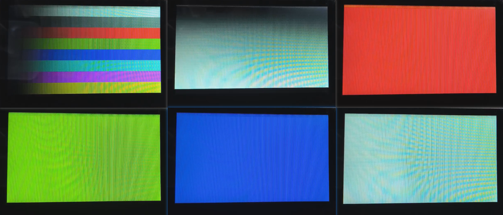
6.1 显示结果展示
As shown in the figure below, if the display is normal, six images will be displayed in sequence, with a 3-second timed loop display