SF32LB52-DevKit-LCD Adapter Board Manufacturing Guide
This document guides you on how to create an adapter board for the SF32LB52-DevKit-LCD development board, which can be used to debug third-party displays, WiFi modules, and more.
QSPI-LCD Interface Adapter Board
The QSPI-LCD adapter board can be used to convert from a 22-pin FPC connector or a 40-pin dual-row pin header.
22-pin FPC Conversion Method
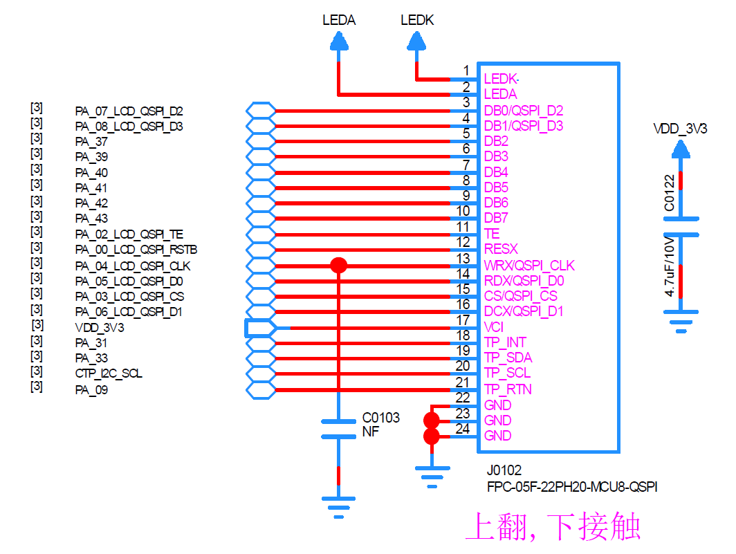
The 22-pin FPC connector on the SF32LB52-DevKit-LCD development board supports MIPI-DBI(8080) and SPI (3/4-wire, 2/4-data) interfaces. The data format can be adapted by configuring the IO MUX through software.
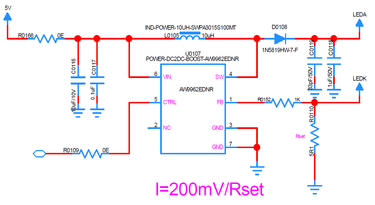
The SF32LB52-DevKit-LCD development board provides an LED driver with a default drive current of 40mA. The drive current can be adjusted by changing the value of R0110 based on the LED circuit structure and current requirements of the LCD display.
Important
The adapter board is connected to the SF32LB52-DevKit-LCD development board via an FPC cable. When designing the adapter board, pay attention to the FPC pin order, which needs to match the signal definitions on the development board.
The VDD_3V3 power supply in the FPC connector can power the screen driver and touch driver on the adapter board.
The IO level of the development board is 3.3V. If the IO level of the driver chip on the LCD adapter board is 1.8V, use a level shift chip to convert the voltage.
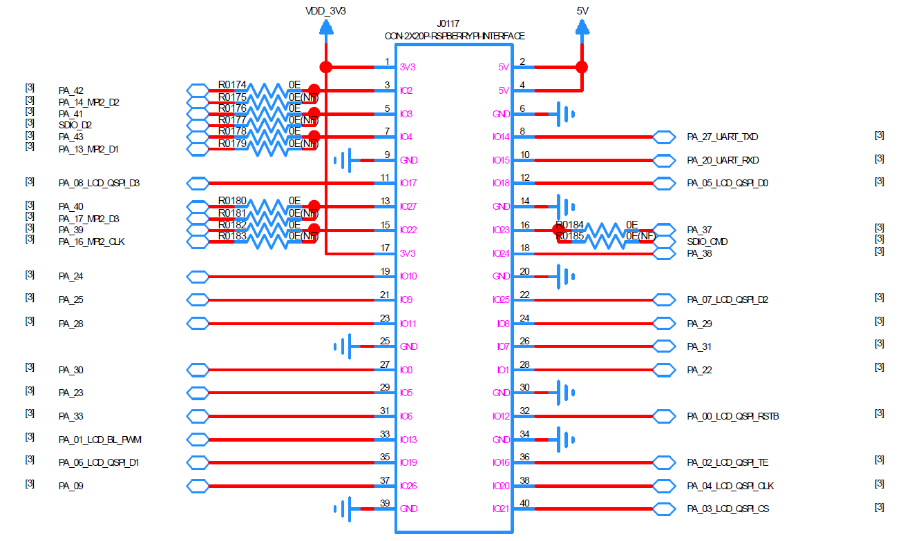
If the adapter board requires a 5V power supply, use a 40-pin dual-row pin header for the interface.
The development board already has resistors in series with the display interface, so no additional resistors are needed on the adapter board.
40-pin Dual-Row Pin Header Conversion Method
Important
The adapter board is connected to the SF32LB52-DevKit-LCD development board via a 40-pin dual-row header, and the adapter board is mounted on top of the development board.
The 3.3V and 5V power from the 40-pin dual-row header can supply power to the screen driver and touch driver on the adapter board.
The IO of the development board is 3.3V level. If the IO level of the driver chip on the LCD adapter board is 1.8V, use a level shift chip to convert the level.
The adapter board should integrate the display backlight circuit.
The development board’s display interface already has resistors in series, so no additional resistors are needed on the adapter board.
MIPI-DBI(8080) Interface Adapter Board
Refer to the QSPI-LCD Interface Adapter Board section