525添加QSPI-LCD实例
1 确认rt-driver工程正常运行
It is recommended to use the rt-driver project for screen adjustment, and confirm that the rt-driver project can run normally and has Log printing before debugging
1.1 Compilation
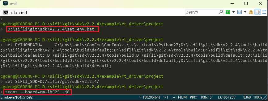
进入example\rt_driver\project目录,右键选择ComEmu_Here弹出Compilation命令串口,依次执行
> D:\sifli\git\sdk\v2.2.4\set_env.bat   #Set compilation environment path
> scons --board=em-lb525 -j8   #Specify em-lb525 module to compile rt-driver project
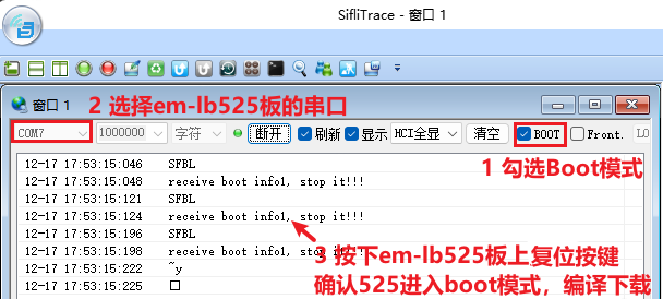
1.2 Enter BOOT mode
确认525em-lb525模块板进入boot模式便于Download,如下图操作
1.3 Download
> build_em-lb525\uart_download.bat

     Uart Download

please input the serial port num:7 #然后Select the serial port number connected to the em-lb525 module to download
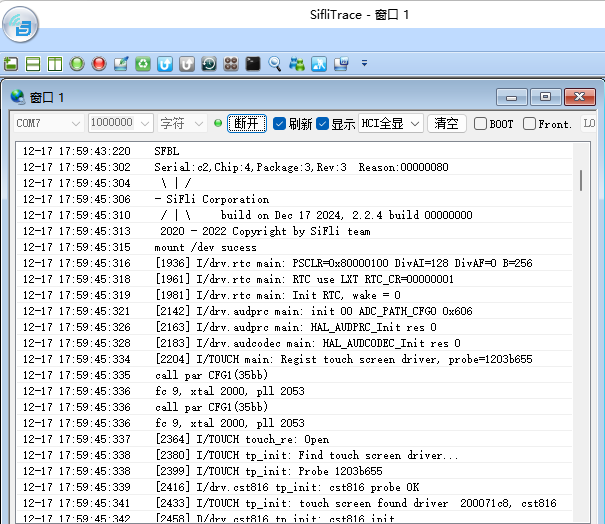
1.4 确认正常LOG
如下图,运行用户程序需要去掉勾选进入BOOT选项,After confirming that the board is running, you can continue to the next step to add a new screen module
2 Add screen driver NV3041A
2.1 Create NV3041A driver
1) 屏驱位置
屏驱动位于sdk\customer\peripherals目录
2) 复制驱动
复制一份其他qspi接口的驱动更名为qspi_nv3041a
2.2 Menuconfig添加NV3041A
1) Modify Kconfig to generate options for this screen in menuconfig
文本编辑器打开sdk\customer\boards\Kconfig_lcd,添加qspi的该屏的选项和分辨率,如下

# menuconfig 生成菜单呈现的选项
        config LCD_USING_TFT_NV3041A
            bool "4.3 rect QSPI LCD(480x272 TFT-NV3041A)" #menuconfig中显示的字符
            select TSC_USING_GT911 if BSP_USING_TOUCHD #If there is TP, you can turn it on. Whether the corresponding TP driver is compiled depends on this macro
            select LCD_USING_NV3041A #spi_nv3041a文件夹内文件是否的Compilation依赖于此宏
            select BSP_LCDC_USING_QADSPI #选择QSPI接口
            select LCD_USING_PWM_AS_BACKLIGHT #是否打开屏的PWM背光,有背光的屏需要打开
            if LCD_USING_TFT_NV3041A
               config LCD_NV3041A_VSYNC_ENABLE #Whether to turn on the TE of the screen, if the screen does not output TE signal after turning on TE, the screen will appear Timeout crash
                    bool "Enable LCD VSYNC (TE signal)" #menuconfig中显示的字符
                    def_bool y #默认值
            endif
# LCD_HOR_RES_MAX is the horizontal resolution of the screen
        default 480 if LCD_USING_TFT_NV3041A
# LCD_VER_RES_MAX is the vertical resolution of the screen
        default 272 if LCD_USING_TFT_NV3041A
# LCD_DPI pixel density, how many pixels per inch of the screen, fill in the default 315 if unknown
        default 315 if LCD_USING_TFT_NV3041A
2) LCD_USING_NV3041A添加
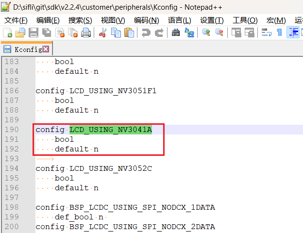
文本编辑器打开文件sdk\customer\peripherals\Kconfig,添加如下
config LCD_USING_NV3041A #Add this configuration so that it can be selected in Kconfig
    bool
    default n
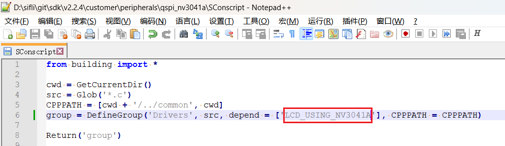
3) SConscript修改
文本编辑器打开文件customer\peripherals\qspi_nv3041a\SConscript,修改宏LCD_USING_NV3041A,这样该目录下的*.c和*.h文件就能加入Compilation
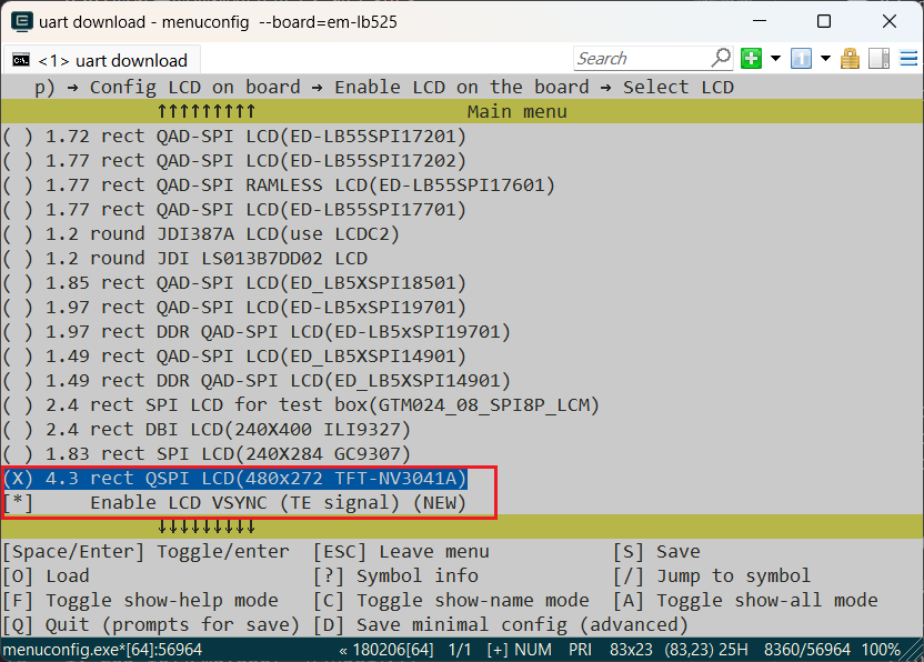
2.3 Menuconfig选中NV3041A
以上步骤完成后,Compilation窗口输入下面命令,并Select the newly added nv3041a screen
menuconfig --board=em-lb525(打开menuconfig窗口) 在这个路径下(Top) → Config LCD on board → Enable LCD on the board → SelecCD选中刚添加的屏,示例如下,保存退出,即选中了qspi_nv3041a目录下屏驱动参加Compilation
3 生成SourceInsight工程
In order to easily view the code participating in the compilation, you can generate a list of files for the entire rt-driver project participating in the compilation, and then import it into Source Insight for easy viewing. This chapter can be skipped
3.1 生成文件List
命令scons --board=em-lb525 --target=si生成si_filelist.txt
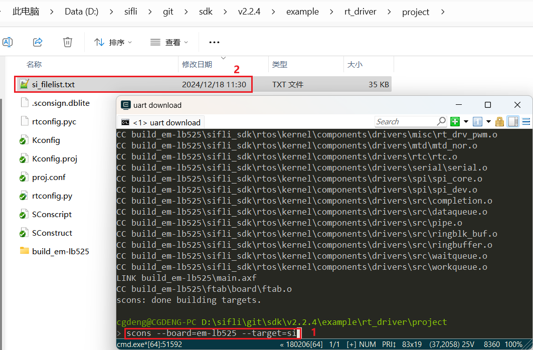
3.2 文件List导入
打开Source Insight导入si_filelist.txt进入工程

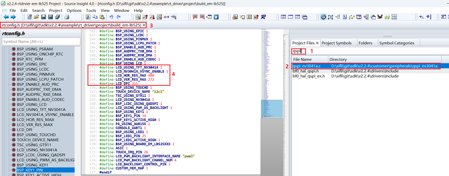
3.3 查看屏驱是否生效
可以在SI(Source Insight)工程中查看rtconfig.h对应宏是否生成和是否已经包含了qspi_nv3041a.c加入Compilation
4 屏硬件连接
4.1 Ribbon connection
如果购买的是匹配的屏幕模组,直接Ribbon connection到插座即可,如下图
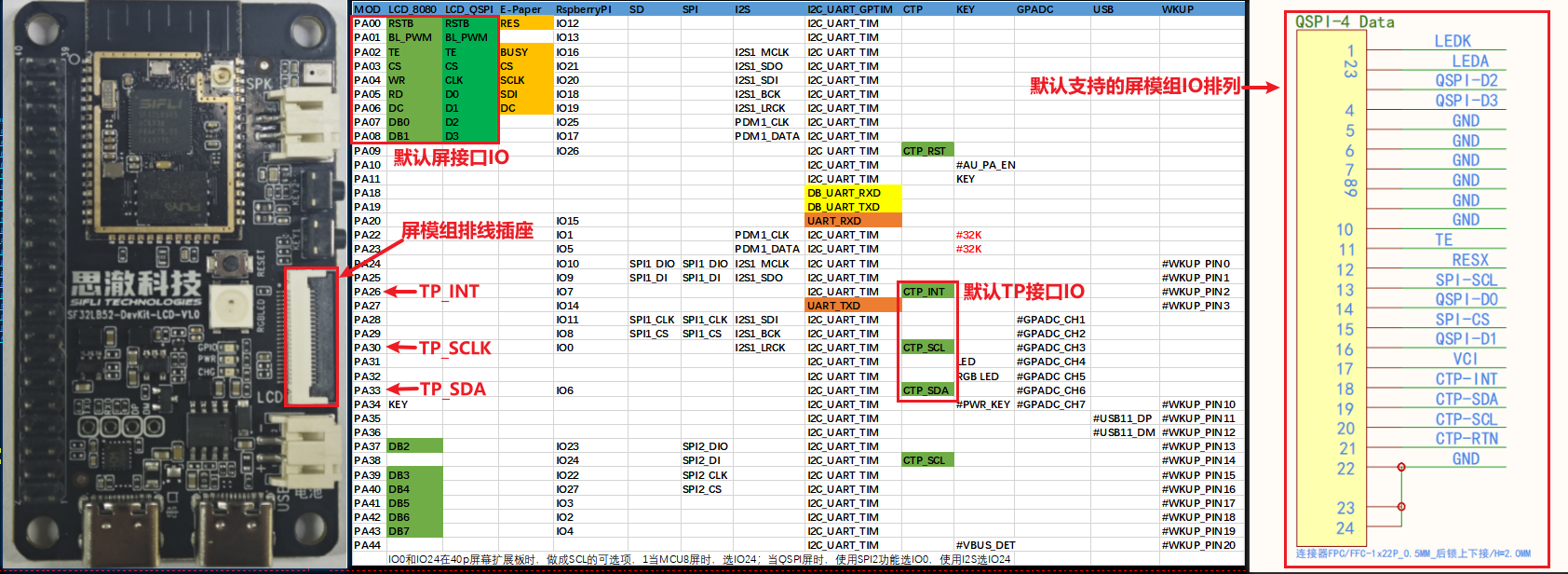
4.2 Flying wire connection
如果新的屏幕模组,排线排列不一致,就需要自己设计排线转接板或者从插针飞线调试。
The design of the adapter board can refer to SF32LB52-DevKit-LCD Adapter Board Production Guide
5 Screen driver configuration
5.1 Default IO configuration
如果采用的默认IO,此处可以跳过
5.1.1 IO模式设置
LCD uses LCDC1 hardware to output waveforms and needs to be configured to the corresponding FUNC mode,
For each IO, which Funtion can refer to the hardware documentation DownloadSF32LB52X_Pin_config
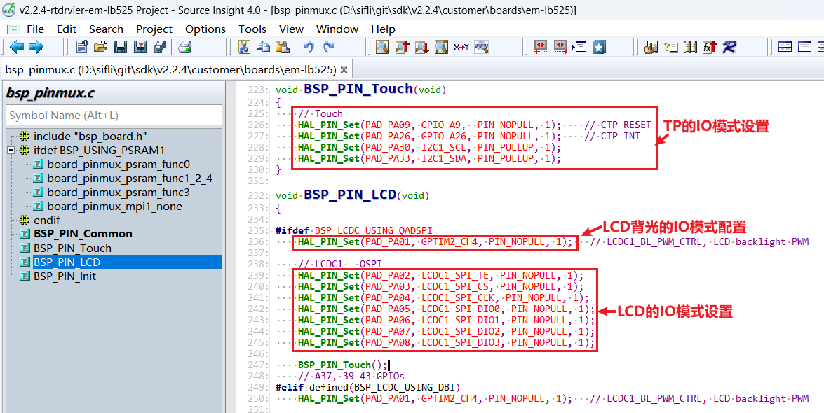
The RESET pins of LCD and TP are in GPIO mode, so they are configured as GPIO mode by default
 HAL_PIN_Set(PAD_PA00, GPIO_A0,  PIN_NOPULL, 1);     // #LCD_RESETB
 HAL_PIN_Set(PAD_PA09, GPIO_A9,  PIN_NOPULL, 1);     // CTP_RESET
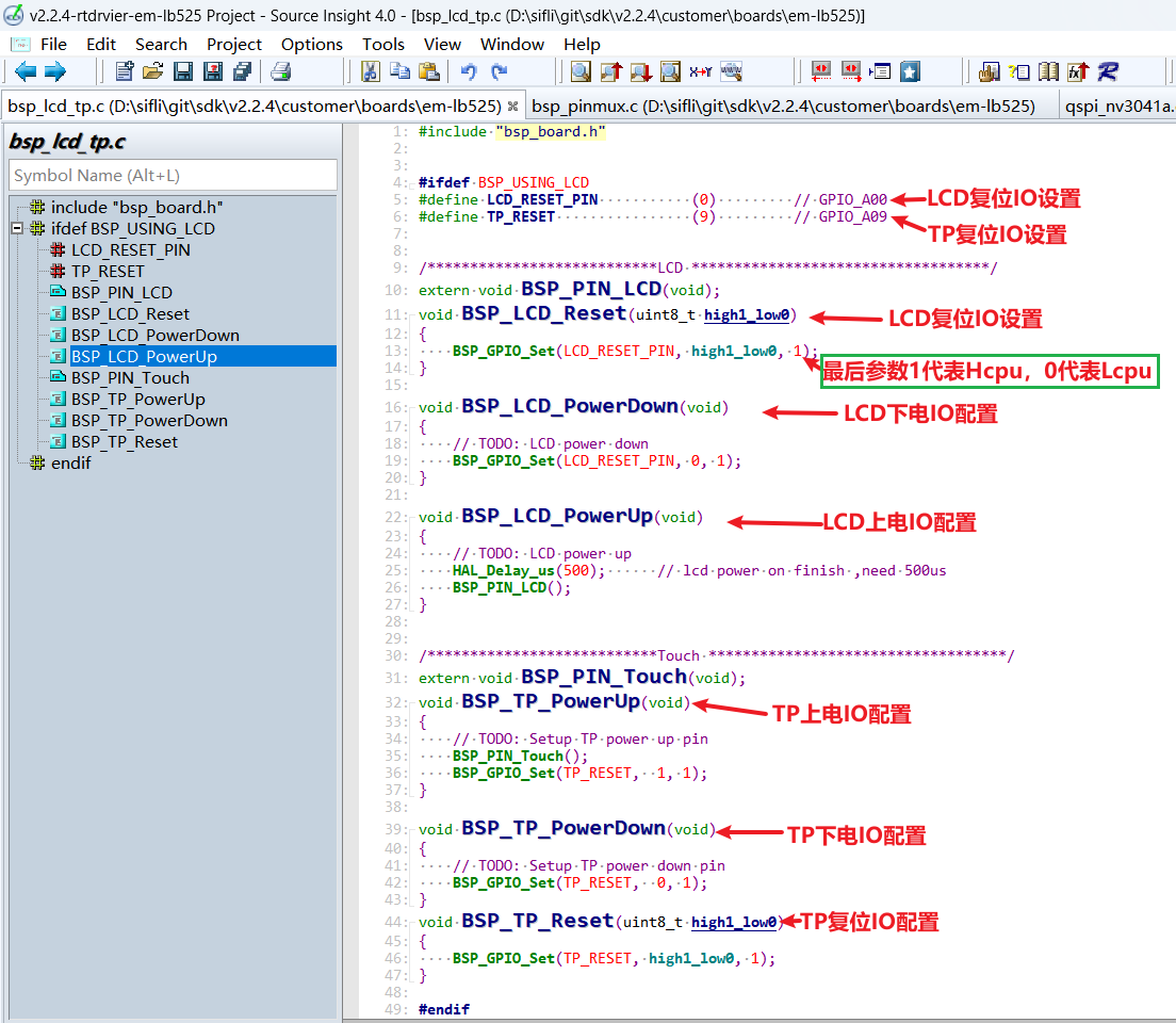
5.1.2 IO上下电操作
下面是Power-on LCD initialization process
rt_hw_lcd_ini->api_lcd_init->lcd_task->lcd_hw_open->BSP_LCD_PowerUp-find_right_driver->LCD_drv.LCD_Init->LCD_drv.LCD_ReadID->lcd_set_brightness->LCD_drv.LCD_DisplayOn
It can be seen that the power-on BSP_LCD_PowerUp is before the screen driver initialization LCD_drv.LCD_Init
Therefore, it is necessary to ensure that the LCD power supply has been turned on in BSP_LCD_PowerUp before initializing the LCD
5.1.3 Backlight PWM configuration
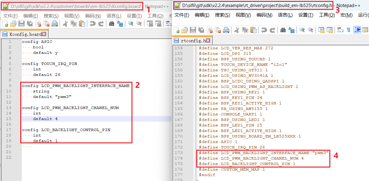
The pwm software has a default configuration, configured in the file customer\boards\em-lb525\Kconfig.board, and this configuration of Kconfig.board will generate the following three macros in rtconfig.h after compilation
//PWM3需要打开GPTIM2,PWM和TIMER对应关系,可以查看FAQ的PWM部分或者文件`pwm_config.h`
#define LCD_PWM_BACKLIGHT_INTERFACE_NAME "pwm3" //pwm设备名
#define LCD_PWM_BACKLIGHT_CHANEL_NUM 4 //Channel 4
#define LCD_BACKLIGHT_CONTROL_PIN 1 //PA01
Using PWM3 requires the output of GPTIM2 (located at Hcpu), and it is also necessary to confirm whether the following macros in rtconfig.h are effective
#define BSP_USING_GPTIM2 1 //如果用PWM3,需要menuconfig --board=em-lb525打开
#define RT_USING_PWM 1
#define BSP_USING_PWM 1
#define BSP_USING_PWM3 1 //如果没有,需要menuconfig --board=em-lb525打开
如下文件pwm_config.h中pwm3和GPTIM2的对应关系
#ifdef BSP_USING_PWM3
#define PWM3_CONFIG                             \
    {                                           \
       .tim_handle.Instance     = GPTIM2,         \
       .tim_handle.core         = PWM3_CORE,    \
       .name                    = "pwm3",       \
       .channel                 = 0             \
    }
#endif /* BSP_USING_PWM3 */
The software defaults PA01 to output PWM waveform from the "pwm3" device of GPTIM2, with the default configuration at
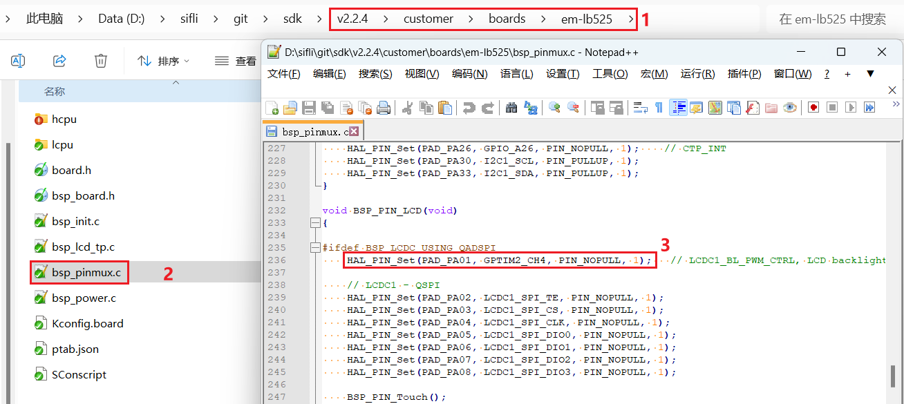
HAL_PIN_Set(PAD_PA01, GPTIM2_CH4, PIN_NOPULL, 1); // LCDC1_BL_PWM_CTRL, LCD backlight PWM
备注:
After configuring through the function HAL_PIN_Set, the correspondence between GPTIM2_CH4 and PA01 will be established, specifically reflected in the register configuration hwp_hpsys_cfg->GPTIM2_PINR,如下图:
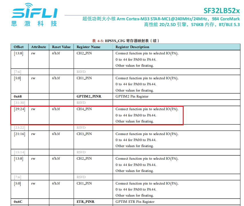
It can be seen that it can be configured as CH1-CH4 output, and must be PA00-PA44 port
5.2 屏驱复位时序
The following delays are critical and need to refer to the initialization timing of the screen drive IC related documents, modify with caution
    BSP_LCD_Reset(1);
    rt_thread_mdelay(1);    //延时1ms
    BSP_LCD_Reset(0);       //Reset LCD
    rt_thread_mdelay(10);   //延时10ms
    BSP_LCD_Reset(1);

    /* Wait for 200ms */
    rt_thread_mdelay(120);  //延时120ms
5.3 屏驱寄存器修改
The initialization register configuration of each screen drive IC varies greatly. It is necessary to follow the register parameters provided by the screen factory, write to the screen drive IC through QSPI according to their SPI timing, and pay special attention to the delay length requirements after registers 0x11 and 0x29
    parameter[0] = 0x16;
    LCD_WriteReg(hlcdc, 0x92, parameter, 1);

    parameter[0] = 0x16;
    LCD_WriteReg(hlcdc, 0xB2, parameter, 1);

    parameter[0] = 0x00;
    LCD_WriteReg(hlcdc, 0xff, parameter, 1);

    LCD_WriteReg(hlcdc, 0x11, parameter, 0); // internal reg enable
    rt_thread_mdelay(60);

    LCD_WriteReg(hlcdc, 0x29, parameter, 0); // internal reg enable
    rt_thread_mdelay(120);
5.4 屏驱参数配置
.lcd_itf : Select LCDC_INTF_SPI_DCX_4DATA to indicate QSPI 4-wire mode
.freq :Select 36000000, indicating that the clk main frequency of QSPI is 36Mhz. This clock should be selected based on the highest clock supported by the screen drive IC. The higher the clock, the shorter the time to send data per frame, and the higher the frame rate
.color_mode :Choose between RGB565 or RGB888 format
.syn_mode :Choose whether to enable TE anti-tearing function. If TE is enabled and the screen drive IC has no TE signal, the screen will not be sent, and a Timeout crash will occur. It is recommended to disable TE during early debugging
.vsyn_polarity :Choose the polarity of TE
.vsyn_delay_us :Choose how long after the TE waveform arrives, LCDC1 starts sending data to the screen drive IC
.readback_from_Dx : When reading Chipid via QSPI, choose which signal line among D0-D3 the data from the screen drive IC is output from(参照屏驱IC手册)
static LCDC_InitTypeDef lcdc_int_cfg_qadspi =
{
    .lcd_itf = LCDC_INTF_SPI_DCX_4DATA,
    .freq = 36000000,                          // 实际频率为Hcpu的整数分频后频率,240Mhz(HCLK)/7 = 34.28Mhz
    .color_mode = LCDC_PIXEL_FORMAT_RGB565,    // RGB565 format

    .cfg = {
        .spi = {
            .dummy_clock = 1,
#ifndef DEBUG
            .syn_mode = HAL_LCDC_SYNC_VER,     //Enable TE, Prevent tearing
#else
            .syn_mode = HAL_LCDC_SYNC_DISABLE, //Disable TE, For debugging
#endif /* LCD_LCD_VSYNC_ENABLE */
            .vsyn_polarity = 1,
            .vsyn_delay_us = 0,
            .hsyn_num = 0,
            .readback_from_Dx = 0,             //qspi read from d0, ( 0-3: d0-d3 )
        },
    },
};
6 Compilation烧录Download结果
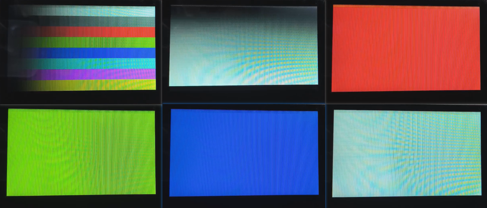
6.1 显示结果展示
As shown in the figure below, if the display is normal, there will be 6 kinds of images displayed in a 3-second timed loop