Firmware flashing tool Impeller
Overview
Impeller is a flashing and calibration tool for SiFli Technology chip platforms used on production lines, and it can also be used as a daily flashing tool. This tool runs on Windows, requires no installation, and can be used directly by opening Impeller.exe. The tool provides the following functions:
Firmware IMG flashing
Generating and flashing MAC/SN and other information
48M crystal calibration and battery measurement calibration
FLASH erase
Supports parallel processing of 16 channels.
Supports both UART and JLINK SWD methods (serial mode is recommended).
For detailed tool usage instructions, refer to “Impeller User Guide.pdf” in the doc folder of the Impeller tool package. Only the flashing procedure is described here.
Tool Download
Click to download the Impeller tool package.
Flashing environment
Hardware environment: PC + hardware development board + Type-C USB cable;
Software environment: Windows system + Impeller tool + firmware package;
SF32LB5x-LCD development board flashing steps
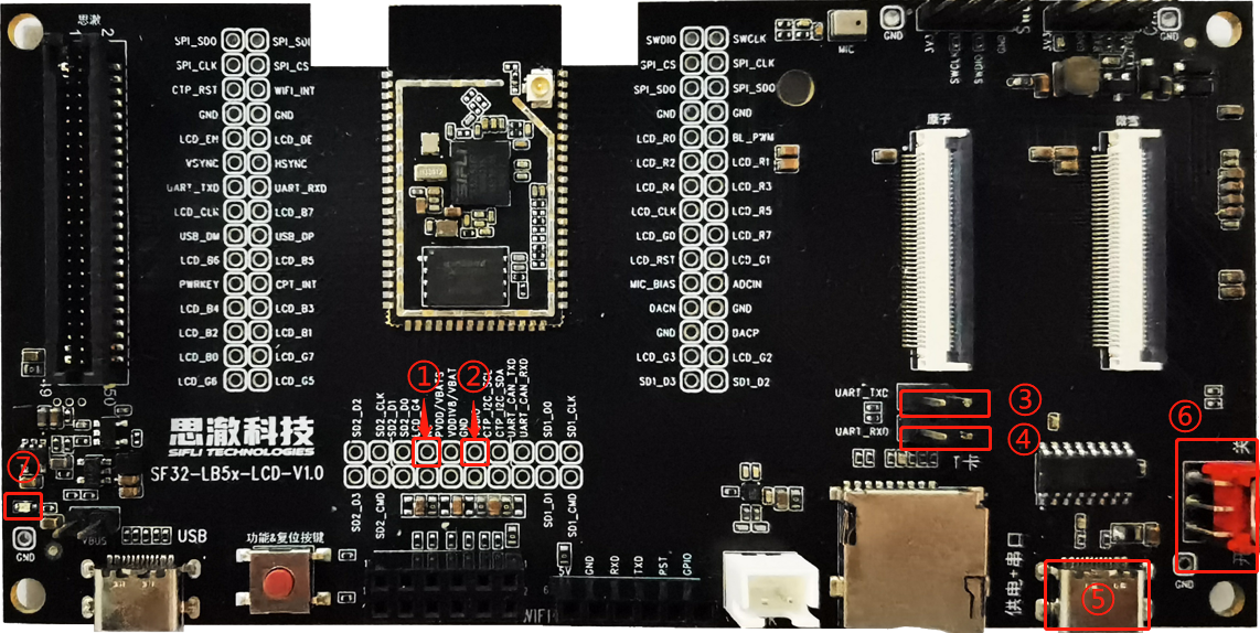
The following figure shows the front view of the SF32LB5x-LCD development board:
\
Pull bootmode high by connecting the corresponding pins ① and ② on the development board, so that the development board enters boot mode during startup;\
The pins at positions ③ and ④ on the development board must be connected with jumper caps to ensure that the download serial port is connected properly;\
Use a Type-C USB cable to connect the corresponding USB port ⑤ on the development board to the PC;\
Turn on the corresponding switch ⑥ and set it to the “ON” position. At this point, the power indicator ⑦ will light up, and a serial port number can be seen enumerated in the PC Device Manager;\
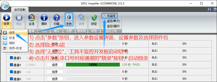
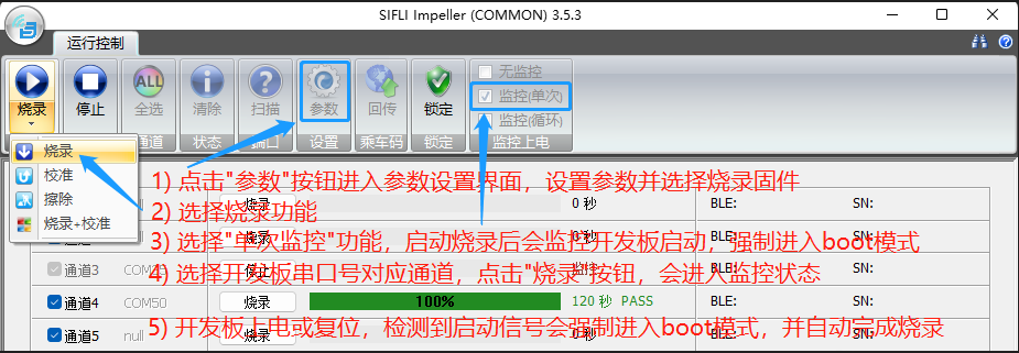
Open the Impeller tool and program according to the figure below:
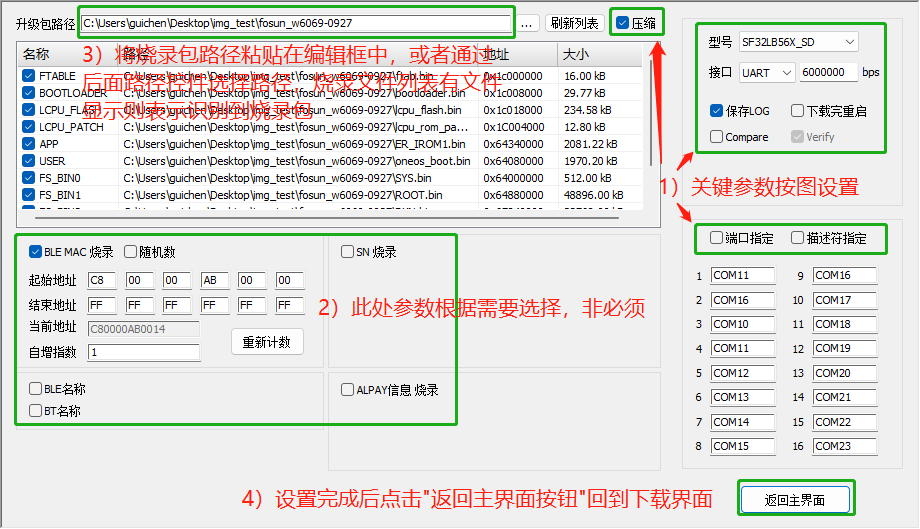
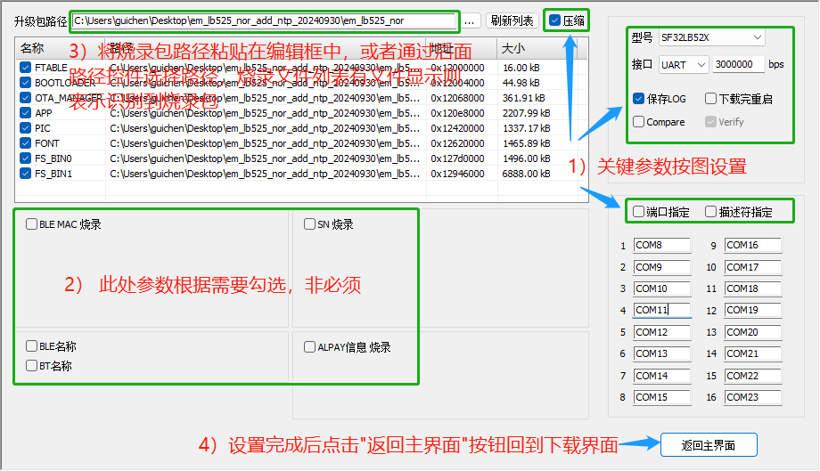
The parameter settings page in step 1) in the figure above is configured as shown in the figure below:
6) Note: After the download succeeds, disconnect the corresponding pins ① and ② on the development board, and power on again to start normally;
SF32LB52-DevKit-LCD development board flashing steps
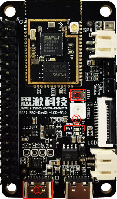
The following figure shows the front view of the SF32LB52-DevKit-LCD development board:
\
Use a Type-C USB cable to connect the corresponding USB port ① on the development board to the PC. At this time, the power indicator ② will light up, and an enumerated serial port number can be seen in Device Manager on the PC;\
Open the Impeller tool and program according to the figure below:
The development board reset in step 5) in the figure above is performed by pressing the development board reset button ③
The parameter settings page in step 1) in the figure above is configured as shown in the figure below:
\
Note: The 52x platform has no bootmode pin. Entering boot mode is handled by the tool through serial commands, so the tool occupies the flashing serial port while in monitoring mode. The preceding process uses one-shot monitoring mode, meaning that after flashing is started, flashing is performed when development board startup is detected, and the serial port is released after completion. If development board startup is never detected, the serial port remains occupied, and you must manually click the “Stop” button in the tool to exit monitoring mode.
Common issues and suggestions
Q1: The board is connected to the PC, but no serial port number is enumerated.
Confirm whether the Type-C USB cable supports data transfer or is damaged.
Confirm whether the Type-C USB cable is connected to the correct port on the development board. Refer to the flashing steps.
Older Windows systems may require driver installation. The USB-to-serial chip on the development board is WCH’s CH34X series.
Q2: A serial port is enumerated on the PC, but it cannot be displayed in the Impeller tool.
Confirm that on the parameter setting page of the Impeller tool, the selected “Interface” type is UART and “Port specified” is not checked.
Click the “Scan” button in the tool to rescan ports.
Q3: After pasting the firmware path on the Impeller parameter setting page, the file list is empty.
Confirm whether the pasted path is correct and whether a downfile.ini or ImgBurnList.ini file exists under the path. If it does not exist or the file content is empty, contact the firmware package provider for confirmation.
Q4: Flashing fails quickly after it starts (within 8 seconds).
Confirm whether the serial port is opened and occupied by other software. Other software must not occupy the serial port during flashing.
Confirm whether the serial port corresponding to the selected channel is the port enumerated by the development board.
Q5: Flashing fails regularly during the process, for example always failing when the download reaches 20%.
Enter the Impeller parameter setting page and check whether the download address in the download file list exceeds the address range of the development board. That is, confirm whether the firmware package matches the development board.
Flashing logs are saved under the log/channel/date folder in the Impeller tool directory. You can simply check the last printed messages, or directly consult an FAE for resolution. In general, causes include abnormal soldering of external FLASH, abnormal power control, unsupported drivers, and so on.
Q6: Flashing is unstable; sometimes it succeeds and sometimes it fails.
Make sure the flashing operation is performed completely according to the preceding flashing steps.
Check whether the Type-C USB cable is damaged or whether the USB connector on the development board is loose.
On the Impeller parameter setting page, reduce the serial baud rate to 1000000 and check whether normal operation can be restored.