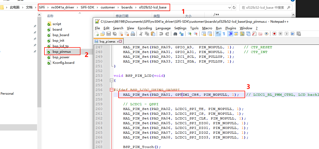
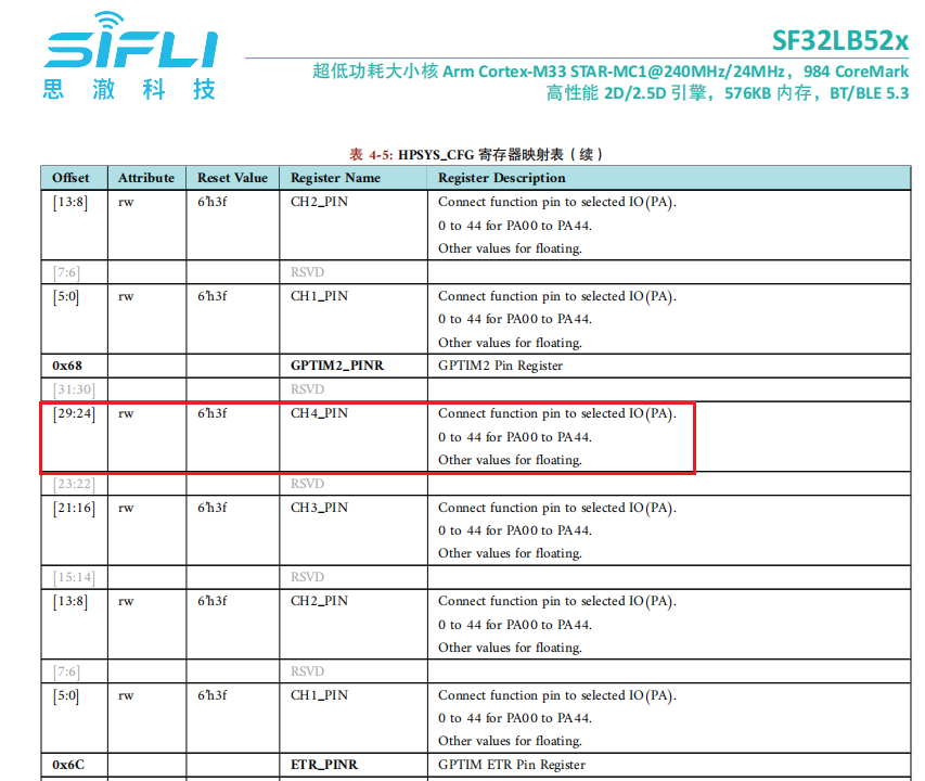
SF32LB52x-DevKit-LCD Add SPI-LCD Example (External)
1 Confirm the rt-driver Project is Running Normally
It is recommended to use the rt-driver project for screen debugging. Before debugging, confirm that the rt-driver project can run normally and print logs.
1.1 Compilation
Enter the example\rt_driver\project directory, right-click and select ComEmu_Here to pop up the compilation command serial port, and execute the following commands in sequence:
> D:\sifli\git\sdk\v2.2.4\set_env.bat   # Set the compilation environment path
> scons --board=sf32lb52-lcd_n16r8 -j8   # Compile the rt-driver project for the sf32lb52-lcd_n16r8 module

1.2 Enter BOOT Mode
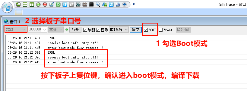
Confirm that the sf32lb52-lcd_n16r8 module board is in boot mode for easy downloading, as shown in the following figure:
1.3 Download
> build_sf32lb52-lcd_n16r8\uart_download.bat

     Uart Download

please input the serial port num:7 # Then select the serial port number connected to the sf32lb52-lcd_n16r8 module for downloading
1.4 Confirm Normal LOG
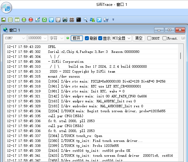
As shown in the following figure, uncheck the BOOT option to run the user program. After confirming that the board is running, you can proceed to the next step to add the new screen module.
2 Add Screen Driver gc9107
2.1 Create gc9107 Driver
Add the project and modify the Kconfig.proj file in the new screen driver folder
sdk-demo
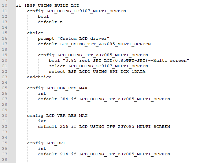
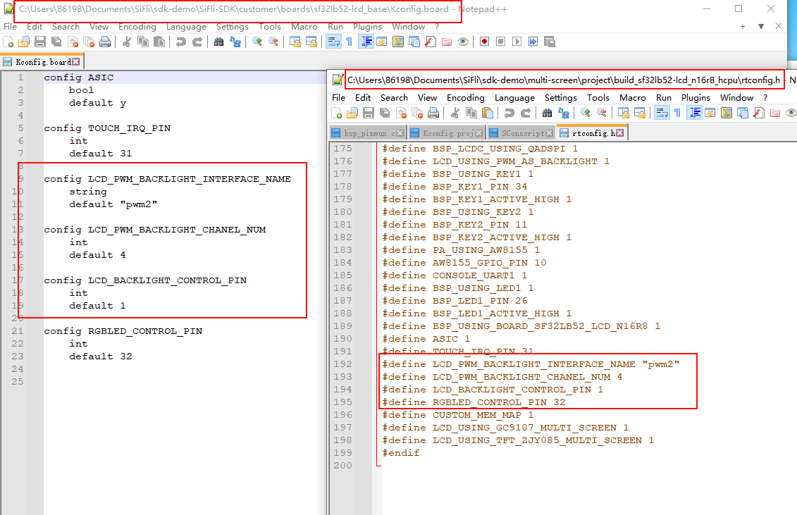
CopySDK\example\rt_driver(if you already have an external project, you can directly modify and add it in the project), and rename it tomulti_screenoutside the SDK. Modify theKconfig.projfile inprojectto add the following content:
#APP specific configuration.

comment "------------Project configuration-----------"

if !BSP_USING_BUILT_LCD
    ···
endif
Modify the
proj.conffile
Add
# CONFIG_BSP_USING_BUILTIN_LCD is not setinproject\proj.confto use the external screen driver and disable the internal screen driver in the SDK.
If you want to use the external screen driver for a specific board or the internal screen driver, you can create a new file in the project directory, for example,sf32lb52-lcd_n16r8/proj.conf, and add# CONFIG_BSP_USING_BUILTIN_LCD is not setorCONFIG_BSP_USING_BUILTIN_LCD=y.
Copy the driver
The internal screen driver of the SDK is located insdk\customer\peripherals. Copy anotherspiinterface driver and place it in the newly created screen driver foldersdk-demo, and rename it toqspi_gc9107
4.2 Screen Driver Reset Timing
The following delays are critical and should be carefully adjusted according to the initialization timing of the screen driver IC.
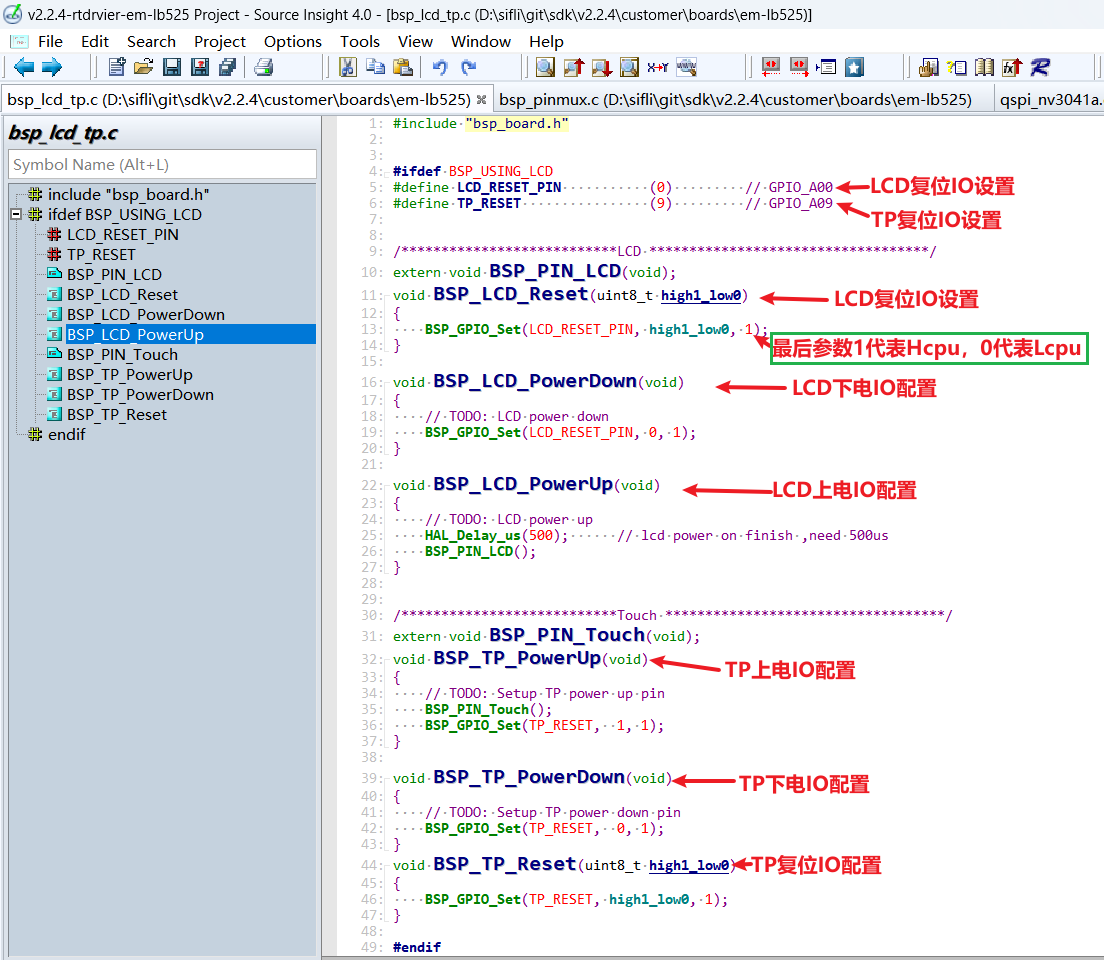
    BSP_LCD_Reset(0);// Reset LCD
    HAL_Delay_us(20);
    BSP_LCD_Reset(1);
4.3 Screen Driver Register Modification
The initialization register configuration for each screen driver IC can vary significantly. You need to follow the register parameters provided by the screen manufacturer and write them to the screen driver IC in sequence according to their SPI timing, paying special attention to the delay requirements after writing to register 0x11.
    LCD_WriteReg_More(hlcdc, 0x11, parameter, 1);
    LCD_DRIVER_DELAY_MS(120);
LCD_WriteReg_More(hlcdc, 0xFE, parameter, 0); // internal reg enable LCD_WriteReg_More(hlcdc, 0xEF, parameter, 0); // internal reg enable
#### 4.4 Screen Driver Parameter Configuration
- .lcd_itf : Select LCDC_INTF_SPI_DCX_1DATA for SPI 1-line mode<br>
- .freq : Select 48000000, indicating the SPI clock frequency is 48 MHz. This clock should be chosen based on the highest clock supported by the screen driver IC. The higher the clock, the shorter the time to send each frame, and the higher the frame rate.<br>
- .color_mode : Choose between RGB565 and RGB888 format<br>
- .syn_mode : Choose whether to enable the TE (Tear Effect) prevention function. If TE is enabled and the screen driver IC does not have a TE signal, it will not send data to the screen, causing a Timeout and system hang. It is recommended to disable TE during initial debugging.<br>
- .vsyn_polarity : Choose the polarity of the TE signal<br>
- .vsyn_delay_us : Choose the delay in microseconds after the TE waveform arrives before LCDC1 starts sending data to the screen driver IC<br>
- .readback_from_Dx : Choose which signal line (D0-D3) the screen driver IC uses to output data when reading the Chipid via QSPI (refer to the screen driver IC manual)<br>
```c
static LCDC_InitTypeDef lcdc_int_cfg =
{
    .lcd_itf = LCDC_INTF_SPI_DCX_1DATA,
    .freq = 48000000,
    .color_mode = LCDC_PIXEL_FORMAT_RGB565,
    .cfg = {
        .spi = {

            .dummy_clock = 0,
            .syn_mode = HAL_LCDC_SYNC_DISABLE,
            .vsyn_polarity = 0,
            .vsyn_delay_us = 0,
            .hsyn_num = 0,
        },
    },

};
5 Compilation and Download Results
5.1 Display Result Demonstration
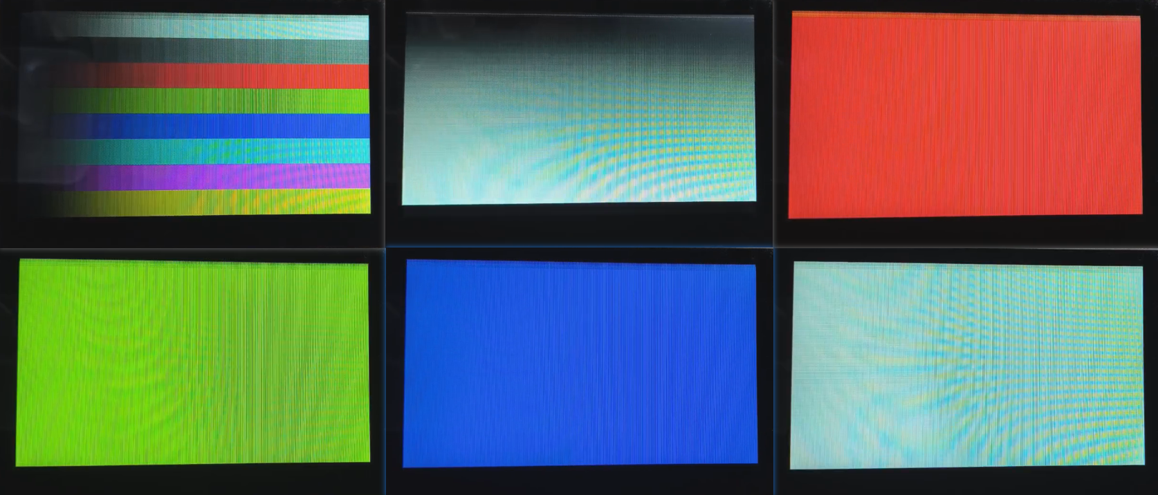
As shown in the figure below, if the display is normal, it will show 6 images in sequence, with a 3-second loop.
